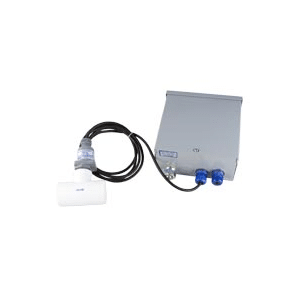
Model SDC-101
Download SDC-101 Installation Instructions
The Problem
- Failure to establish programmed flow after pump turn on signal has been applied.
- Failure to maintain proper flow during normal operation due to line clogging, line rupture, incorrect valve positioning, etc.
The Solution
- Insertion of an SDC-101 shut down control in the input power line of pumps, heaters, valves, etc., that are flow critical will interrupt power automatically upon loss of flow.
- Power will remain off until the problem has been corrected and proper flow re-established.
- Loss of pump prime is a persistent fluid system problem. A flow switch at the pump output is a viable solution, except that it presents a “Catch 22″ situation, i.e. lack of flow at start up will not allow the flow switch to supply power to the pump. A manual push to start or automatic time delay relay switch in parallel with the flow switch is required to supply power to the pump motor during startup. After the pump is up to speed the parallel switch kicks out and the flow switch takes over flow monitoring. Model SDC-101 is provided with a parallel variable time delay relay switch/flow switch combination to provide pump protection during startup as well as the continuous phase of operation.
SDC-101 modules may be connected to monitor:
- Critical points in simple one pump systems or, in series, with pumps, heaters, valves, etc., so that failure of any part will shut the whole system down.
- Isolated or remote components and sub-systems.
For Use In
- Chemical process industry
- Sanitation
- Food processing
- Aerospace ground support systems
- Water treatment
- Mining
- Agriculture
- Transportation
Additional Features:
- Continuous adjustment of time delay cycle.
- 120/240 VAC and DC power options
- Rain resistant housing for rugged, industrial usage
- Can be used in mobile vehicles, ships, trains, etc.
Operational Features:
- Supplied pre-wired and ready for immediate installation
- All components UL listed or recognized
- Input and output power lines are quickly and easily attached to 30 AMP terminal block
- Terminal block positions are numbered and wiring is color coded for easy, fast and accurate installation and servicing.
- Performance checks are quick and straightforward using an uncomplicated, standard multimeter.
Specifications
Control Box
Rain resistant type 3R – UL listed J&P Box 312J, P/N 70233A
Time Delay Relay
Operation
When rating voltage is applied to the input, the timing cycle begins and the DPDT relay is activated. At the end of the timing cycle, the relay is de-activated and remains in that condition until power is removed from the input. Switching off and then turning on of input power re-starts the timing cycle. This timing sequence will repeat each time the system is turned on.
Input Voltage – 120/240 VAC, 50/60 Hz
Output Contact Arrangement – DPDT
Contact Rating
10 AMP, 1/2 HP @ 120/240 VAC, 50/60 Hz
Standard Time Cycle
1 to 180 seconds, Continuously adjustable
Ambient Operating Temp. Range -5° to 140°F
Termination – 1/4″ quick disconnect terminals
Motor Contactor Specifications
Operating Coil
- 120 VAC or 208-240 VAC 50/60 Hz
- Inrush: 31 VA
- Continuous Use: 7 VA
- Pickup: 90 VAC (120 VAC Coil)
- 170 VAC (208 VA Coil)
- Coil Insulation: class B
- Coil Connections: Double Male 1/4″ quick connect
- Maximum Ambient Temperature: 155°
Output Power Contacts
- Type: DPST – Normally Open
- Contact rating per pole.
Switch Performance Data
Refer to manufacturer’s specification sheets for information regarding performance of:
- Harwil Fluid Flow switches
- Harwil Air Flow switches
- Pressure switches
- Motion Limit switches
- Proximity Switches, etc. which may be used in conjunction with, but are not included with, the SDC-101 module.
Complete operating instructions. Mechanical and Electrical installation drawing and a numbered parts list is supplied with each unit.
Maintenance and checkout is a snap for your present personnel using an uncomplicated standard test meter.
Terminal Strip – 812 Series
Electrical Rating
- Rated voltage – 1600 Volts RMS
- Current rating – 30 AMPS
Wire Size
Will accommodate lugs for wire sizes AWG #14 to #12
Hardware
- Screws and terminals – brass, nickel plated
- Solder terminals – brass, hot-tinned
Molded Material
- G.P. phenolic (94V-0).
- UL Recognized
- UL File No. E47811
- CSA File No. 21356
- Installation drawing and a numbered parts list is supplied with each unit.
- Special One Day Delivery Available.


Reviews
There are no reviews yet.